I discovered juvenile science fiction around age eight when I got my first library card in Houston. I devoured the Tom Swift novels, Heinlein and others. My grandfather gave me SF paperbacks from the fifties, opening a new dimension for me. Inspired by my reading, I wrote my own stories, abysmal simulations of pulp SF. A few years later, I fell in love with Ray Bradbury when I read his short story “The Green Morning.” In middle school, I spent my allowance buying every Bradbury story collection I could find and Tolkien’s novels. When I reached college, a yearbook editor who liked my photos introduced me to SF conventions. The SF world seemed endless then, and it still is.
For several years after graduating with a masters degree in electrical engineering, I continued to write SF short stories. Though I had mastered prose, I knew nothing of storytelling, as the rejection slips proved. Eventually, I stopped pretending that I could write stories and got on with my engineering career. For SF reading, I consumed Omni, Fantasy and Science Fiction, and Asimov’s magazines. But I drifted away from the field for quite some time.
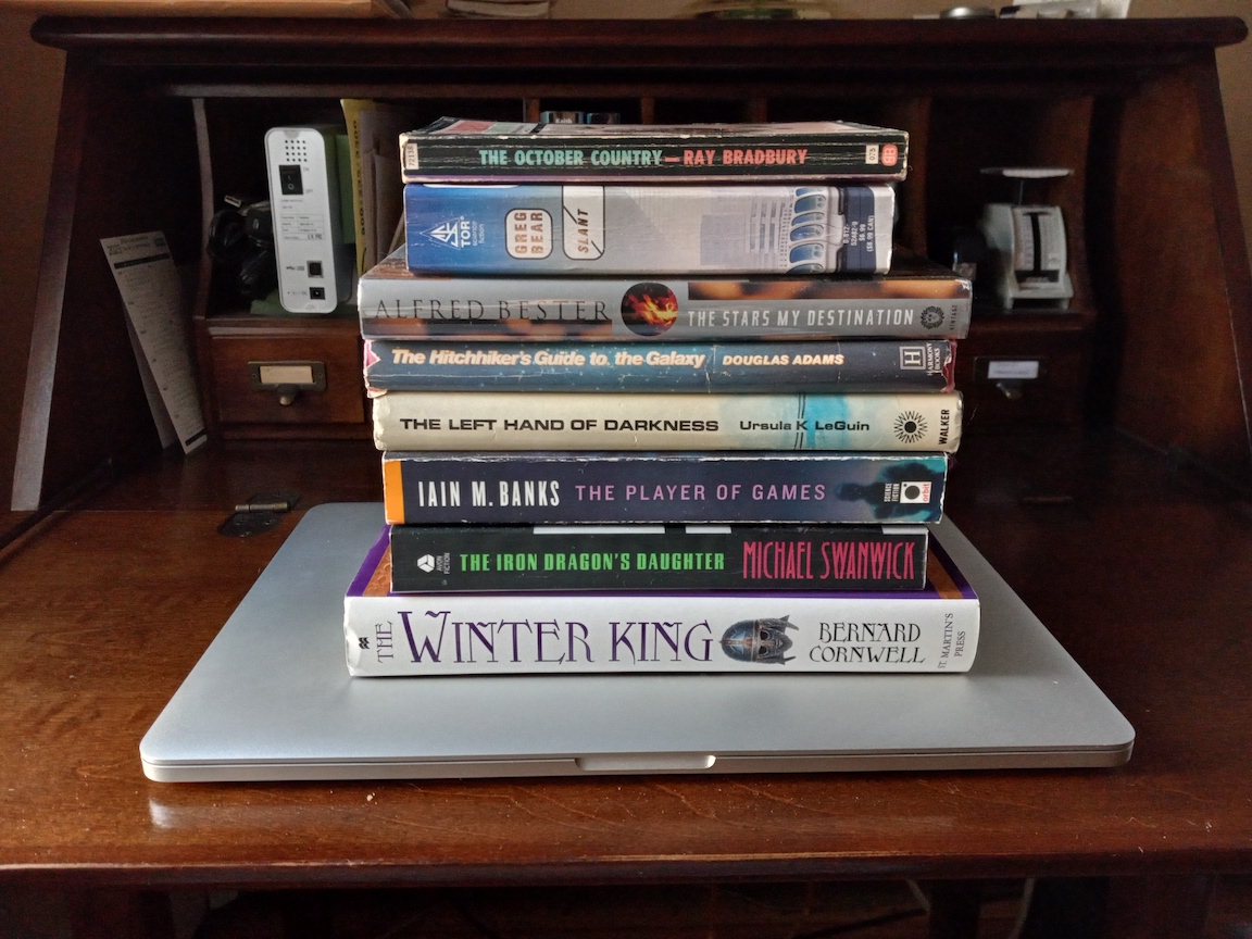
An Iain M. Banks novel rekindled my interest in SF. Sadly, it was too late for me to meet that very talented author. We were born in the same year, but he died far too young. Saddened, but inspired, I read most of Banks’ novels, including his literary collection. Banks remains among my favorite authors, which include Ursula K. LeGuin, Ray Bradbury, Michael Swanwick, Greg Bear, Bernard Cornwell, Douglas Adams, and Alfred Bester.
In 2016, I resolved to learn how to tell stories. Hammering out short story after short story, I got feedback from the online workshop Critters and I again began collecting rejections. Two near misses gave me hope that I was making progress. A year in the StoryGrid Guild delivered essential information about story, but at a steep cost in time, frustration, and money. Following that experience, I found storytelling advice that was easier to absorb and closely aligned with what StoryGrid teaches. The lessons reached a critical mass that convinced me to tackle a novel and to pursue an indie publication route.
My first novel—working title: A Star Apart—is moving ahead. It’s a space opera with themes of community and cooperation. When will it be finished? I’m not sure. My goal is early 2024. Only time will tell.
10 Aug 2023 update: I completed a first draft of A Star Apart in late July. I am now working on a second draft. Progress is slow, but steady.
22 Jan 2024 update: My newsletter, Deep Space Opera, has launched. Join today for a free short story related to my novel! Subscribe now. I’m also editing the second draft of A Star Apart and will be seeking beta readers soon. I’ll ask newsletter subscribers first, when I’m ready for beta readers.
21 Apr 2024 update: Book plans have changed. A Star Apart will remain the first novel in the Alloyed series, but the second book. The first shall tell the origins of the human-quantum chimeric technology that makes Alloying possible. I see book 1 as a collection of novellas and short stories. Writing that collection is now top priority, while work on A Star Apart continues at a slower pace. My publication goal is mid to late summer 2024.